
ABOUT MDL 2.0
The MDL (Minimalist Development Language Specification) has been in existence for over 10 years and since its inception it has had very few changes. Aligned with ArcH's needs, that very often applies the MDL in their daily lives, and after evaluating the considerations of several students and customers, we created version 2.0 of the MDL.
WHY MDL?
To draw the whole team, collaboratively draw the structure and behavior of an application on a paper or whiteboard so that everyone involved (users, developers, infrastructure analysts, etc.) can understand, use it as official documentation from the project. The simplicity of the diagram allows you to make a new design to replace the old one instead of tweaking it.
COMPONENTS MDL 2.0
Currently MDL has 7 components. They are:

USER
This element can represent both physical users (people, areas) and bots, such as an AI.
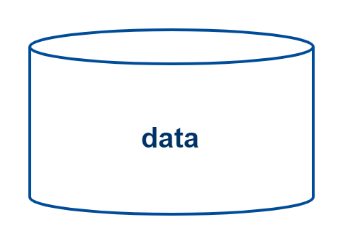
DATA
Represents any source of data existing in our applications.

BACK-END
Generic back-end element. The biggest change was that, previously, this element were only used to describe API's, BFF's and services, but now any back-end system is described by this element

FRONT-END
This is a new element in MDL 2.0, whenever it is necessary to represent a screen/interface, the element used is the front-end.

BLACK-BOX
This element's main purpose is to abstract a component that you don't want to go into the details within your design, removing the need to explain details that are sometimes "unnecessary" for a given architectural design.

PART
Its purpose is to represent subcomponents, that is, to represent parts of a component. It can be used, for example, if you have an interface and want to represent as parts a particular interface, or if you have a service and want to represent it, or you have a database and Represent tables. The level of abstraction is up to you. The Part has the same format as the Layer and the same format received from the FrontEnd. In addition, the Part can represent Tiers and Layers. That way, when we want to represent a large layer, or an inner layer, we use a Part. This gives us Helps to maintain a single level of diagram context, and the level of abstraction can vary.

BOUNDARY
It is the same as Tier. It has the purpose of separating contexts, isolating pieces of the diagram, delimiting a boundary. It serves to delimit a functional space or a space of technical components, it is a way to better organize the diagram.
CONNECTORS
MDL 2.0 has only the link, but it is possible to represent it as a composition, inheritance or as a connection that always occurs (always link). It is possible to insert the arrow in the opposite end of the connector, indicating the direction of information flow. The absence of the arrow in the opposite end of a representation of composition, inheritance or continuous connection indicates that the direction of connection is the same of the composition, inheritance or continuous connection, that is, they go over the arrow.

LINK
Indicates the connection and the direct relationship between the elements. It is also intended to indicate the sequence and meaning of the communication. It is strongly recommended to put ubiquitous language descriptions in it to macroize the business and number to indicate the sequence in which the business (or technical) flow takes place. This connector accepts the use of the composition representation or specialization in the other end, indicating specialization and link or composition and link.

ALWAYS LINK
If there are something that always happens, like database connection, service registry or security validation, it's recommend use link with a ball with filled background in one of the tips and the arrow of the link in the other indicating that an iteration link between two "always" elements occur in the same way. In this case a ubiquitous explanatory text should be used with the connector, however without sequence numbers.

Specialization
Indicates the inheritance of all the characteristics of the parent element, if the other end does not contain the tip of the link (characterizing specialization and link), it's not allowed to add descriptions and sequence numbers.

VIRTUAL LINK
Indicates that the connection between the elements is weak. For example, a virtual link or tables in a database where the relationship between them is not a true FK (Foreign Key).

Composition
It indicates that the element that receives the tip is composed of related elements, that is, it is a macro-component (maybe even abstract) composed of the others, if the other end does not contain the tip of the link (characterizing composition and link), it's not allowed to add descriptions and sequence numbers.
EXAMPLES


NEWS IN VERSION 2.0
WHAT HAS CHANGED? What ceased to exist
- Behavioral and structural contexts: Now we only have a single context, so everything can be represented in it.
- Micro Batches: This element was rarely used, especially when talking about microservices. So, to avoid differences between microservices, APIs or any other type of core, everything was synthesized in a single element.
- Layer e Tier: There will no longer be the differentiation between Tier's and Layer's, which have also been synthesized into a single element.
WHAT WAS CHANGED?
- The way to represent layers: Now we can use the Part to represent the layers (Tiers and Layers), in addition to being able to be used to compose any element. This allows for greater ease and flexibility.
- The way to represent the frontend: The change was made not to confuse Part and Frontend, being chosen a common component in practically all diagram editors, so that the change will not generate any burden.
- Connectors: Connectors have been kept, but can now be used on ALL elements, including Parts. There is also a greater incentive to use more text in connectors so that they are better "interpretable". Less need for "turn" connectors, as long as the understanding of the drawing is clear.
- Possibility of use of images and icons for component design.
- Using "[" and "]" between conditions and logical expressions that is, how the link between 2 elements occurs.
- All in a single view: Purpose of enabling an evolutionary design. Diagrams can be born functional and be evolved, continued to be more comprehensive and cover the structure. All elements can use a "#"+ text or "<<"+text+">>" to indicate what the element is. For example: a system, a data instance, a table, a technology, etc.
WILL COMPLEXITY INCREASE?
A question that always comes up when we talk about changes. Will complexity increase? No, actually there will be fewer elements and the MDL will only have a single context, and no longer a behavioral context and a structural context. Therefore, the MDL will be further simplified.
HAVE THE POSSIBILITIES BEEN EXPANDED OR REDUCED?
Another point that can generate concern is the design possibilities, if we will have more restrictions with the new version. We can say that the possibilities will be expanded, the MDL has become simpler and more powerful, making it possible to use it in more ways than the previous version. Furthermore, the MDL has not lost its minimalist essence, it still has few elements and few connectors, and with the same flexibility.