INTRODUCTION
When observing the implementation of whole projects making use of MDA, it was diagnosed that to specify and maintain a documentation with the composition of hundreds of Micro-Components making use of standards and frameworks for designer of applications used in the IT market, such as UML, C4 among many others, it was concluded that:
- Drawing and documenting demands a lot of effort, often greater than building some Micro-Component;
- It is necessary to elaborate different designs for each stakeholder besides a meeting to explain to them the drawing;
- Even by making use of agile methodologies involving all stakeholders and the technical team, the lack of visions that made the flow of the business clear, the order in which things happen and the Micro-Components involved, generated gaps in understanding or divergent understandings problems in the application or in its structure.
However, the lack of a ubiquitous notation of understanding and adherence to ceremonies of agile design definitions, generates errors, rework, and significantly increases development time.
And this was the fuel for the creation of a new, ubiquitous, MDA-oriented application designer framework that adheres to agility.
WHY MDL?
To draw the whole team, collaboratively design the structure and behavior of an application on a paper or on a whiteboard so that everyone involved (users, developers, infrastructure analysts, etc.) is able to understand, use it as official project documentation. The simplicity of the diagram allows you to make a new design to replace the old one instead of adjusting it.
CONTEXT VIEWS
Contexts of vision isolate diagrams in two visions with completely different: behavioral and structural.
Although it can be used for high-level definition, MDL is not recommended for data modeling or for designing physical architectures (involving details of components such as firewall, network, balances, etc.).
However, in order to catalog software assets and maintain a living documentation the MDL can be used without problems, even replacing the complex TOGAF notations.
Below are the two types of MDL context view:
- Structural: This context view aims to structurally define the application and its Micro-Components, defining the physical layers, logical, frameworks, toolkits and other components involved.
- Behavioral: This context view unifies business rules, sequence and segregation in micro-components, ideal for specifying the business agile and at the same time the composition in Micro-Components to determine how development will be.
STRUCTURAL CONTEXT VIEWS
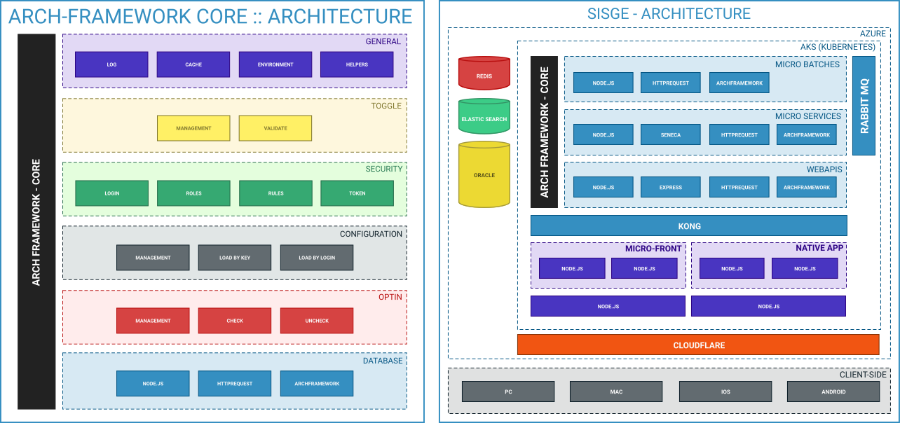
The structural visualization context aims to define the physical and logical layers of a system. It can also be used to define architectural patterns of development.
In this context view there are only 2 elements and 1 connector, listed below:
For a better representation, it is recommended put nested tiers and layers. There are no limits of nested sub-elements.
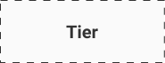
TIER
Represents any type of large layer normally used for physical layers such as clusters, data centers, servers, etc.
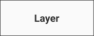
LAYER
Represents any type of layer normally used for logical layers such as Applications or packages and their inner layers, it can also be used to represent tool kits, frameworks and other software dependencies of an application.
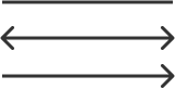
LINK
It is the same connector as the Behavior View Context, however, you can add arrows or not at one or both ends as long as it is necessary to represent the direction of communication between the layers. The use of the connector in the diagram is optional however, highly recommended mainly to represent the relationship between tiers.
BEHAVIORAL CONTEXT VIEWS
The basis of this context view is the UML use case diagram, and it is considered a good practice to segment the drawings in the same way that you segment the use case scenarios. However, it is important not to confuse the diagrams of this context view with the use case diagram as they are in essence completely different.
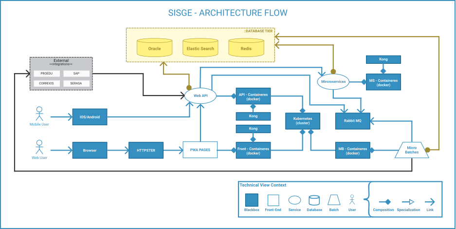
In this context view there are only 6 elements and 3 connectors, listed below:
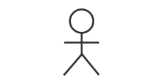
USER
It has the same meaning as the actor in the use case, but should not be used to represent other systems. In the MDL a User can be any person, paper or artificial intelligence that directly or indirectly infers in the system, being able to be protagonist (making input in the diagram) or being impacted by it (receiving outputs).

BLACK-BOX
It represents anything (programs, services, actors, etc.) that receives inputs or outputs from the diagram but which is unknown or which is not necessary to be described it in the current diagram.

FRONT-END
It represents visual interfaces, being a Micro-FrontEnd or any other type of visual interface.
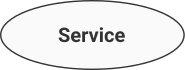
SERVICE
Represents Micro-Services or any type of service, be they file-sharing service, back-end (core), dlls, web services or web apis.
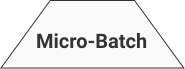
BATCH
Represents Micro-Batches or any type of asynchronous service that performs operations that are too heavy to be synchronous or in batch.
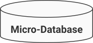
DATABASE
Represents Micro-Database or any type of relational or non-relational source data instance.
CONECTORS

LINK
Indicates the connection and the direct relationship between the elements. It is also intended to indicate the sequence and meaning of the communication. It is strongly recommended to put ubiquitous language descriptions in it to macroize the business and number to indicate the sequence in which the business (or technical) flow takes place. This connector accepts the use of the composition representation or specialization in the other end, indicating specialization and link or composition and link.

ALWAYS LINK
If there are something that always happens, like database connection, service registry or security validation, it's recommend use link with a ball with filled background in one of the tips and the arrow of the link in the other indicating that an iteration link between two "always" elements occur in the same way. In this case a ubiquitous explanatory text should be used with the connector, however without sequence numbers.

SPECIALIZATION
Indicates the inheritance of all the characteristics of the parent element, if the other end does not contain the tip of the link (characterizing specialization and link), it's not allowed to add descriptions and sequence numbers.

COMPOSITION
It indicates that the element that receives the tip is composed of related elements, that is, it is a macro-component (maybe even abstract) composed of the others, if the other end does not contain the tip of the link (characterizing composition and link), it's not allowed to add descriptions and sequence numbers.
EXAMPLES